 Technical paramete
Maximum wind resistance: 52m/s
Maximum snow resistance: 1.5KN/m2
Span range: 0.6-3.2m
System installation angle deviation: ± 2 °
Design standard: AS/NZS1170 ASCE 7-05 DIN1044
GB50797-2012 GB 50017-2003 Steel structure design
Specifications, etc.Performance parameter
Installation site: flat roof or level ground
Body material: Q235B
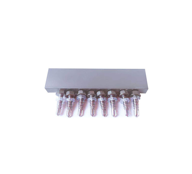
Fastener material: SUS304 or hot-dip galvanized steel
Applicable components: framed or frameless
Applicable arrangement: vertical or horizontal
Warranty period: 10 years
Bracket System Components
Product Features
- Strong compatibility
 The carbon steel bracket system can meet the installation requirements of different specifications of PV modules. At the same time, it is compatible with the different arrangement of components.
 - Safe and reliable
 The carbon steel bracket system mainly uses hot-dip galvanized carbon steel material to effectively prevent corrosion and oxidation. The overall structure of the bracket is stable, wind-resistant, snow-resistant, and shock-resistant, and has safe and reliable characteristics.
 - Low price
 The carbon steel bracket main body material is made of hot-dip galvanized carbon steel, and the price is much better than the traditional aluminum alloy.
Installation instructions
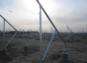
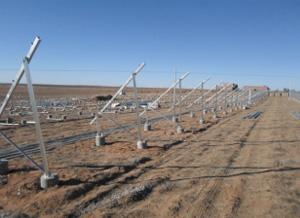
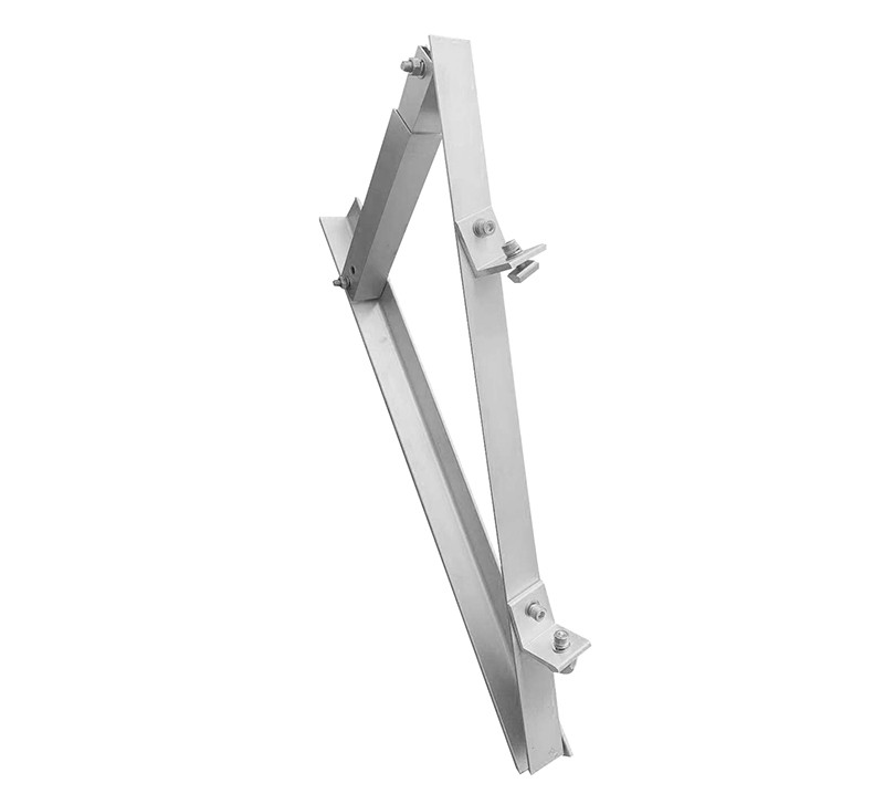
Step1:Installation of carbon steel bracket
Fix the base on the cement foundation with the bolts embedded. As shown in Figure 1 (left); the pre-assembled bracket is unfolded and mounted to the base. As shown in Figure 2 (right).


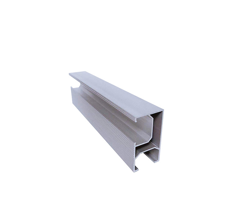
Step2:Installation of purlins
Install the stern plate on the carbon steel bracket before installing the rafter as shown in Figure 3 (left), Figure 4 (middle); place the rafter on the bracket (the side of the opening is facing up) and fix it in the chin rest The board is shown in Figure 5 (right).


If the length of the stringer is not enough, it is possible to connect the plurality of stringers into one piece with a stringer connection. As shown 6

Install the ampule effect diagram, as shown 7

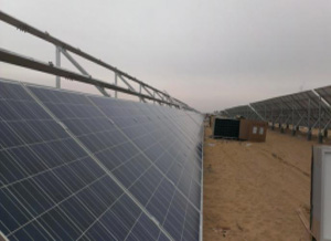
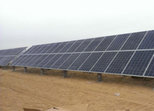
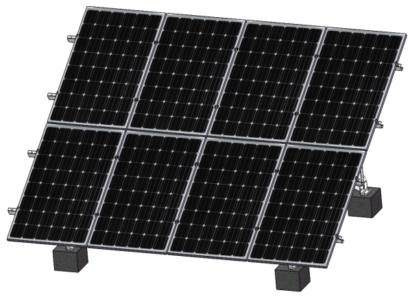
Step3:Installation component
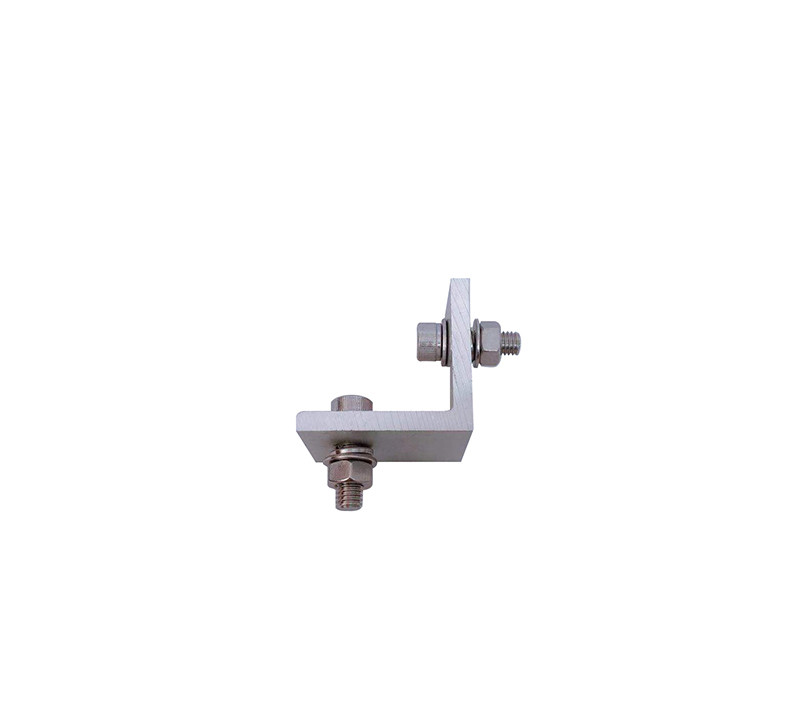
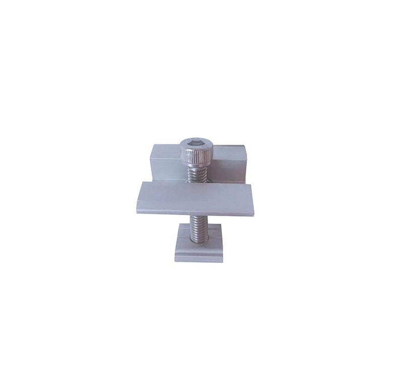
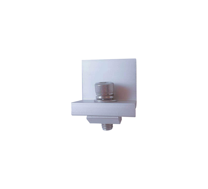
The components are tiled on the rails and the solar panels are installed in a designed position, secured by side clamp assemblies and medium pressure block assemblies. As shown below

Case show